In the realm of Computed Tomography (RE), precision is not limited to image reconstruction; it extends to the very electricity that powers the system’s logic. Even minor fluctuations in DC voltage can trigger catastrophic system hangs or deceptive error codes. This article examines a diagnostic case where a seemingly complex display failure on a Siemens SOMATOM CR was traced back to a simple, yet overlooked, power distribution issue.
1. Clinical Presentation and Symptomology
The unit in question—a SOMATOM CR CT—exhibited a total loss of video output upon initialization. Under normal operating conditions, after the DMC (Display Micro Computer) console is powered on and the graphics card completes its POST (Power-On Self-Test), the screen should initialize with the system identifier "TM2000k."
History:
- Intermittent Failure: The issue had occurred sporadically over the previous month but was usually resolved by a hard reboot.
- Persistent Failure: The frequency of the fault increased until the display remained blank regardless of power-cycling attempts.
2. Diagnostic Methodology and Initial Troubleshooting
Initial hypotheses focused on the most visible point of failure: the graphics subsystem.
- Physical Inspection: The host machine was opened, and the graphics card was extracted. Inspection of the gold fingers, interface pins, and board components revealed no signs of thermal stress or mechanical loosening.
- Gross Power Check: A preliminary measurement of the host power supply unit (PSU) outputs (+5V, -5V, +12V, -12V, +3.3V) was conducted. The rails appeared nominal at the source, leading the team to suspect a faulty graphics card.
- The Swap Test: A known-good graphics card from a spare unit was installed. Surprisingly, the screen remained blank.
Note on Proprietary Hardware: In medical imaging, BIOS-level "Handshaking" or vendor-locked serial numbers often mean a standard swap might not work without software reconfiguration. This complication initially led the team further away from the actual hardware root cause.
3. Deep Dive: Identifying the Voltage Drop
After the failure of the graphics card swap, the focus returned to the Internal DC Distribution. A more rigorous measurement was performed—this time at the load end (the terminal where the card receives power) rather than the source.
- Source Voltage: Measured at 5.3V (slightly high, but within the PSU's adjustment range).
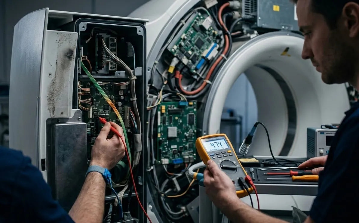
- Load Voltage: Measured at a mere 4.7V at the card input terminal.
A 0.6V drop in a 5V logic circuit is critical. Most TTL (Transistor-Transistor Logic) components require a minimum of 4.75V to function reliably. At 4.7V, logic gates enter an "undefined state," causing the graphics processor to fail to initialize the display.
4. Root Cause: The "Invisible" Resistance
Tracing the 5V line back from the board, the team identified a fuse holder (F8) in the distribution path. Upon extracting the fuse, the following was observed:
- Oxidation/Carbonization: The contact points between the fuse and the holder had turned black due to micro-arcing and oxidation over years of service.
- Contact Resistance: This carbon layer acted as a resistor, dissipating voltage as heat and causing the 0.6V drop.
5. Resolution and Verification
The fuse holder was meticulously cleaned and oxidized layers were removed. A new fuse was installed, and the voltage was re-measured:
- Post-Repair Voltage: 4.98V at the board terminal.
- System Result: The DMC passed self-test immediately, and the "TM2000k" prompt reappeared. The system returned to full operational status.
Conclusion and Professional Takeaway
This case serves as a vital reminder for Field Service Engineers (FSEs): Never trust a voltage reading at the source alone. In high-precision medical equipment, "nominal" power at the PSU does not guarantee "clean" power at the logic board. Always verify the Voltage at the Load. The accumulation of contact resistance in fuse holders, backplanes, and connectors is a silent killer of CT uptime. Precision in measurement is the only way to avoid unnecessary board replacements and extended downtime.